
WDP-03 · Material-efficient panels
Hollow Core WPC Door Panel Production Line: Saving Material Without Sacrificing the Door
Hollow chambers can reduce material use and weight, but they also make the die and cooling process less forgiving. The savings are real only when the internal walls stay straight and the panel surface remains suitable for finishing.
Technical review: BENK Machinery · Updated 6 November 2026
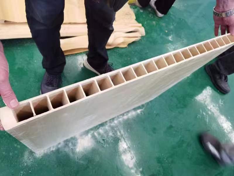
A hollow-core WPC door board is not simply a solid board with material removed. The internal ribs, outer wall thickness and cooling path all affect stiffness, screw holding and surface quality. If the die distributes melt unevenly, one side can run thinner than the other before the board reaches the calibrator.
This page is for producers who want a lighter panel without turning every order into a quality dispute. The focus is on what a hollow-core line must control and what to ask before the die is cut.
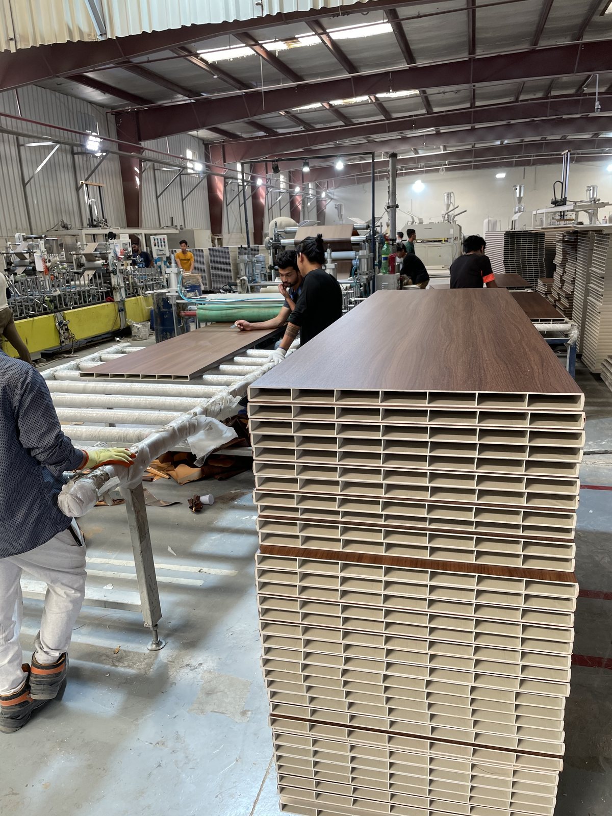
What changes when the core is hollow
The die has more internal geometry, so flow balance becomes more important. Material has to fill the outer walls and ribs at the same time without leaving weld lines or weak corners. Vacuum calibration then has to support the outside shape while the ribs cool from both sides.
The finished board may look flat on the face while the internal walls are distorted. That is why visual inspection alone is weak. A useful trial includes section samples, wall-thickness checks and a simple stiffness or handling test.
- Outer wall too thin after calibration
- Internal ribs leaning or collapsing
- Visible sink marks on the face
- Uneven cooling between the edges and centre
- Screw pull-out or edge damage during assembly
The line settings that keep the section stable
Melt pressure should be steady before the line speed is increased. The calibrator needs enough vacuum zones to pull the outer surface against the tooling without crushing the internal section. Cooling water should be controlled through the run, not adjusted by feel.
The haul-off also matters. A wide hollow panel can be damaged by excessive clamping force. The puller should hold the outside edges without marking the decorative face, and the cutter should support the panel while it cuts.
How BENK approaches a hollow-core project
BENK reviews the internal drawing, outer wall thickness, rib layout and required panel length before confirming the line. The door-board die and vacuum calibration table are then matched to the section rather than selected from a width alone.
Where the buyer wants both solid and hollow boards, the line can be discussed as a multi-product setup. The practical changeover scope should be clear from the start, including die handling, temperature recovery and downstream adjustment.
- Die design based on the internal section drawing
- Vacuum zones arranged to support the outer walls
- Haul-off pads and pressure chosen for the panel surface
- Cutting support to protect the hollow edge
- Sampling procedure for wall thickness and rib condition
Production sequence
From material preparation to finished panel
- 01
Review the door section
Confirm the outer wall, rib pattern and assembly points.
- 02
Select the extruder
Match plasticising capacity to the hollow section and target output.
- 03
Design the die
Balance flow to the outer walls and internal ribs.
- 04
Set calibration vacuum
Support the outer shape without collapsing the core.
- 05
Control cooling
Remove heat evenly through the full vacuum table.
- 06
Pull and cut
Handle the panel without crushing the edges or marking the face.
- 07
Inspect the section
Cut samples and check wall thickness, rib position and surface condition.
Reference window
Reference specification and planning range
The figures below are a starting point for discussion. The final line specification should follow the approved panel drawing, material formula and trial result.
| Item | Reference / planning note |
|---|---|
| Reference widths | 600 / 800 / 900 / 1000 mm |
| Reference thickness | 40-50 mm |
| Core type | Hollow core with square or customer-specific internal chambers |
| Extruder reference | SJZ80/156 or SJZ92/188 depending on width and output |
| Calibration | Six-metre vacuum table with adjustable vacuum zones |
| Output reference | Approx. 350-800 kg/h by model and section |
How BENK fits the project
Where the BENK line supports the result
BENK can configure a hollow-core WPC door panel line around the internal section and target output. The die and calibration design are confirmed from the section drawing, and the final wall thickness is verified during the trial.
Buyer checklist
What to settle before you compare quotations
- Send a dimensioned section drawing, not only a photo of a finished door.
- Ask how the die will balance material to the thinnest internal wall.
- Confirm the vacuum zones and support rollers for the panel width.
- Agree on a section-sampling method before shipment.
- Check whether the intended hardware and hinge positions suit the hollow core.
Questions buyers ask
WPC door panel line FAQ
Is a hollow WPC door panel weaker than a solid panel?
Not necessarily. Stiffness depends on the outer wall, rib layout and overall section. A well-designed hollow panel can be suitable for many interior door applications while using less material.
Can BENK make different hollow-core patterns?
The die can be designed around a customer-specific section once the drawing and material are confirmed. Complex changes should be reviewed for flow balance and tooling cost.
Why do sink marks appear on hollow panels?
Sink marks can come from uneven wall thickness, local cooling differences or insufficient pressure in part of the die. The die and calibration setup should be reviewed together.
What output can be expected?
Output depends on the panel width, section, formulation and downstream setup. BENK reference models range from about 350 to 800 kg/h; the exact figure is confirmed during the trial.
Project brief
Tell us the panel, not just the machine.
Send the panel drawing, material formula, target output and factory location. BENK can then review the line configuration against the actual product.