RTP Equipment Selection
RTP Line Selection by Pressure & Size
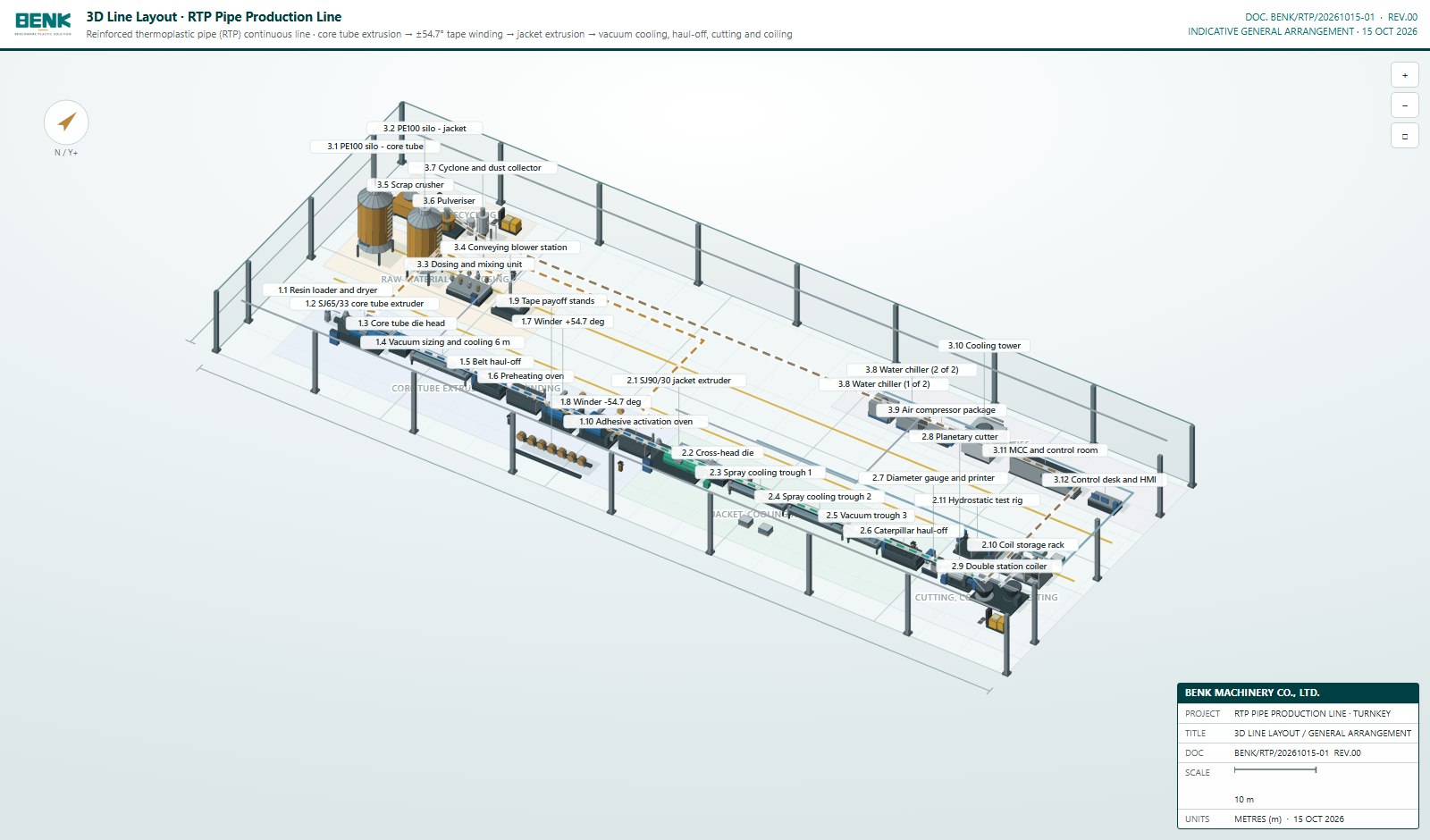
Use the pipe size, pressure class, reinforcement schedule and target output to define the right RTP line configuration. The baseline below matches BENK’s confirmed RTP line concept: core tube extrusion, balanced tape winding, heating and activation, jacket extrusion, cooling, haul-off, cutting, testing and coiling.
Confirmed line baseline
63–250 mm outside diameter
Up to 32 MPa with aramid reinforcement
Line speed 0.5–8 m/min
33 equipment items / 34 machines
8 m eaves height
±54.7° balanced tape winding
How pressure class affects the line
| Pipe requirement | Typical line implication | Confirm before quotation |
|---|---|---|
| 1.6–6.4 MPa standard range | Two winding heads laying a balanced ±54.7° helix | Tape type, tape width, layer count and pipe size |
| 4–8 reinforcement layers | Additional winding capacity; layer sequence and line speed must be matched | Whether a second pair of winding heads is required |
| Higher pressure / aramid design | Reinforcement and tension control are reviewed for the higher load case | Design pressure, safety factor, tape specification and qualification plan |
| Different liner or jacket material | Extruder, die, heating and cooling configuration may change | Material grade, melt behaviour and process window |
The ±54.7° angle is the balanced-winding baseline for this line concept. The final angle, tension and layer schedule must be confirmed against the pipe design and qualification requirements.
Three-section line configuration
10 equipment items / 10 units
- Resin vacuum loader and dryer
- SJ65/33 single screw extruder, 45 kW
- Core tube die head and sizing
- Vacuum sizing and cooling
- Belt haul-off, first pass
- Preheating oven, 18 kW
- Two reinforcement tape winders, 11 kW each
- Steel strip and glass tape pay-off
- Adhesive activation oven, 15 kW
11 equipment items / 11 units
- SJ90/30 jacket extruder
- Cross-head die
- Spray cooling troughs
- Vacuum trough
- Caterpillar haul-off
- Diameter gauge and printer
- Planetary cutter
- Double station coiler
- Coil storage rack
- Hydrostatic test rig
12 equipment items / 13 units
- PE100 silos for core and jacket
- Dosing and mixing unit
- Conveying blower station
- Scrap crusher and pulverizer
- Cyclone and dust collector
- Water chillers and cooling tower
- Air compressor package
- MCC and control room
- Control desk and HMI
Selection inputs
- Pipe inside and outside diameter range
- Design pressure and safety factor
- Operating temperature and fluid
- Liner material and wall thickness
- Reinforcement type, tape width and layer count
- Jacket material and thickness
- Target output and line speed
- Coil inner diameter, width and weight
- Workshop length, height and power supply
- Inspection, traceability and project standard
Turn the pipe matrix into a confirmed line
Send the pipe size matrix, pressure class, reinforcement schedule and target output. BENK will confirm the line configuration, utility load, layout and equipment scope.