RTP Pipe Production Line
A complete continuous line that turns PE100 resin into spoolable reinforced thermoplastic pipe: core tube extrusion, ±54.7° reinforcement winding, jacket extrusion, cooling, haul-off, cutting and coiling — one line, one control system, one supplier.
What an RTP pipe production line does
RTP (reinforced thermoplastic pipe) is a spoolable composite pipe: a thermoplastic core tube carries the fluid, continuous reinforcement layers carry the pressure, and an outer thermoplastic jacket protects the reinforcement. Because the pipe is wound onto coils instead of being jointed every 6 or 12 metres, a gathering line that needs hundreds of welded joints in steel can be installed in a fraction of the time.
This line produces that pipe continuously. A single screw extruder forms the PE100 core tube, which is vacuum sized and cooled, then reheated. Two servo ring winders lay steel strip, glass fibre tape, aramid tape or polyester tape at the balanced ±54.7° angle, so the reinforcement carries both hoop and axial load. An infrared activation oven re-melts the outer skin of the core tube so the reinforcement bonds without an adhesive film, and a second extruder applies the outer jacket through a vacuum calibrated cross-head. The finished pipe is cooled, measured, cut, coiled and pressure tested on the same line.
Every drive, heater and winder is coordinated by one control system, so changing from one pipe specification to the next is a recipe change in the HMI — not a mechanical rebuild. Winding angle, tape tension, line speed and cooling are stored per product, which keeps the pressure rating repeatable from coil to coil.
Typical reference: 110 mm inside diameter, 4.0 MPa working pressure, 2 reinforcement layers at ±54.7°, 12 m/min nominal haul-off, 500 m coil.
What makes this line different
- Balanced ±54.7° cross winding in one pass, not a wrapped tape overlap
- Closed loop tape tension from 200 to 1500 N, held while the coil diameter grows
- IR activation instead of an adhesive film, so the pipe stays a single thermoplastic material
- Vacuum calibrated jacket for a round, void free outer layer
- Servo synchronisation from the die to the coiler, so wall thickness does not drift
- In line diameter and pressure verification before the coil leaves the line
Technical specification
The figures below describe a standard line. Pipe dimensions, pressure rating, number of winding heads and output are set by your pipe specification — send us the pipe size matrix and pressure class and we will confirm the exact configuration.
| Item | Specification |
|---|---|
| Pipe structure | PE100 or PE-RT core tube + 2 – 4 continuous reinforcement layers + PE outer jacket |
| Pipe size | 50 – 200 mm inside diameter (63 – 250 mm outside diameter) |
| Reinforcement | Steel strip, glass fibre tape, aramid tape or polyester tape, selected for the pressure class |
| Winding angle | ±54.7° balanced winding; 2 winders as standard, 4 winders for high pressure pipe |
| Working pressure | 1.6 – 6.4 MPa standard; up to 32 MPa with aramid reinforcement |
| Service temperature | −40 °C to +80 °C continuous (PE-RT core tube for higher short term temperature) |
| Line output | 120 – 350 kg/h depending on pipe size, wall thickness and reinforcement content |
| Line speed | 0.5 – 8 m/min |
| Delivery form | Coils up to 500 m for 50 – 110 mm; 12 m straight lengths above 160 mm |
| Installed power | Approximately 400 kW (drives and heaters) |
| Floor space | 96 × 36 m, 8 m eaves height, level floor, 400 V / 50 Hz supply |
| Operators | 2 – 3 per shift including coil handling |
| Equipment | Specification |
|---|---|
| Core tube extruder | SJ65/33 single screw, 45 kW AC motor with inverter, grooved feed section, barrier screw, 5 heating zones, melt pressure control |
| Core tube die | Spiral mandrel die for 50 – 200 mm with interchangeable sizing sleeves; vacuum and internal air ports |
| Sizing and cooling | 6 m vacuum sizing and spray cooling trough, two vacuum pumps, air wiper, three axis adjustable tool rail |
| First haul-off | Two belt caterpillar haul-off, servo synchronised, 0.3 – 12 m/min |
| Preheating | Hot air with IR boost, 3 controlled zones, 90 – 120 °C surface temperature |
| Winding heads | 2 × servo ring winder, traversing carriage, closed loop tape tension 200 – 1500 N, quick change spools |
| Jacket extruder | SJ90/30 single screw, 90 kW AC motor with inverter, grooved feed bush, barrier screw, melt pump optional |
| Jacket die | Cross-head die with vacuum calibration, replaceable flow inserts, water cooled mandrel |
| Jacket cooling | 2 × 6 m spray cooling troughs plus 3 m vacuum sizing trough with closed loop vacuum control |
| Second haul-off | Caterpillar haul-off, servo drive, 0.5 – 8 m/min, pressure controlled by servo cylinder |
| Measurement | Laser diameter gauge, 0.01 mm resolution with ovality display and closed loop feedback; inkjet printer |
| Cutting and coiling | Planetary cutter with servo carriage; double station coiler, coil diameter up to 2.6 m with traversing guide |
| Testing | Hydrostatic pressure test rig up to 20 MPa with automatic ramp, hold, burst detection and data logging |
| Upstream and utilities | 2 × 40 m³ silos, gravimetric dosing 0.3 % accuracy, pneumatic conveying, crusher and pulveriser, 2 × 30 HP chillers, cooling tower, air compressor, MCC room |
All figures are indicative engineering values for a standard configuration and are confirmed in the technical proposal against your pipe specification.
Equipment advantages on this line
Eight things that decide whether a composite pipe line holds its pressure rating shift after shift.
Balanced ±54.7° winding
Two winders lay the reinforcement as a balanced cross helix. Hoop stress and axial stress are carried by the same tape, which is what keeps the pressure rating stable when the pipe is coiled and later straightened on site.
Closed loop tape tension
The tape tension is measured and corrected continuously from 200 to 1500 N. Without it the inner layers are loose and the outer layers are over-tensioned, and the pipe fails at a lower pressure than the design value.
Bonding without adhesive film
The IR activation oven re-melts the outer skin of the core tube immediately before winding, so the reinforcement bonds directly to the PE. No adhesive layer, no third material, no delamination path.
Two extruders, one control system
The core tube and jacket extruders, both haul-offs, the winders, the cutter and the coiler run from one PLC with one recipe. Changing pipe specification does not mean re-setting four independent control panels.
Vacuum calibrated jacket
The cross-head die is vacuum calibrated, so the outer jacket is round and free of voids over the full pipe length — the point where a composite pipe usually starts to corrode or to snag during installation.
Servo synchronised from die to coiler
Line speed is governed by the winders and followed by both haul-offs. Wall thickness and winding pitch stay constant when the coiler accelerates, so the pipe is uniform from the first metre to the last.
Diameter and pressure verification in line
A laser gauge with closed loop feedback keeps the diameter on target, and the hydrostatic test rig pressure tests the finished coil before it leaves the line. Test data is logged against the coil number.
Built around your pipe specification
Die, sizing sleeves, winding pitch, tape width, haul-off capacity and coil size are selected from your pipe size and pressure matrix, not from a fixed catalogue line.
Process flow
Eight continuous steps from resin to a pressure tested coil.
- Resin drying, dosing and conveying
- Core tube extrusion — SJ65/33
- Vacuum sizing and spray cooling
- Preheating to bonding temperature
- ±54.7° reinforcement winding
- Adhesive activation and jacket extrusion
- Cooling, diameter control and haul-off
- Cutting, coiling and pressure testing
See the line before it is built
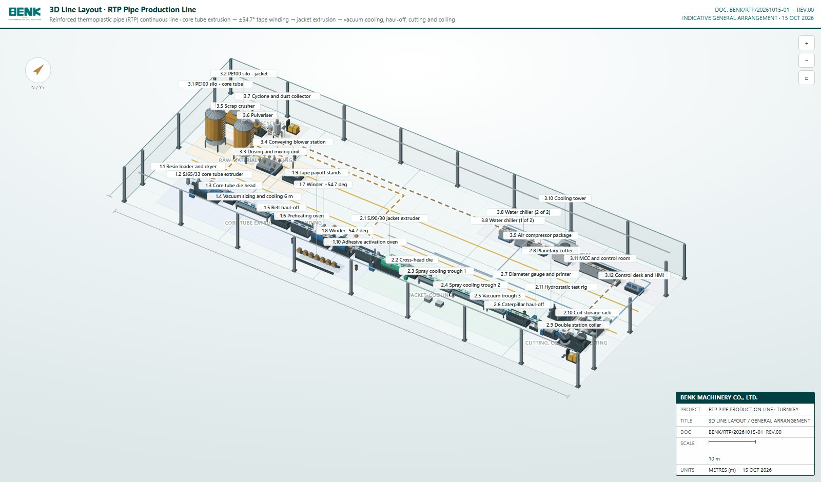
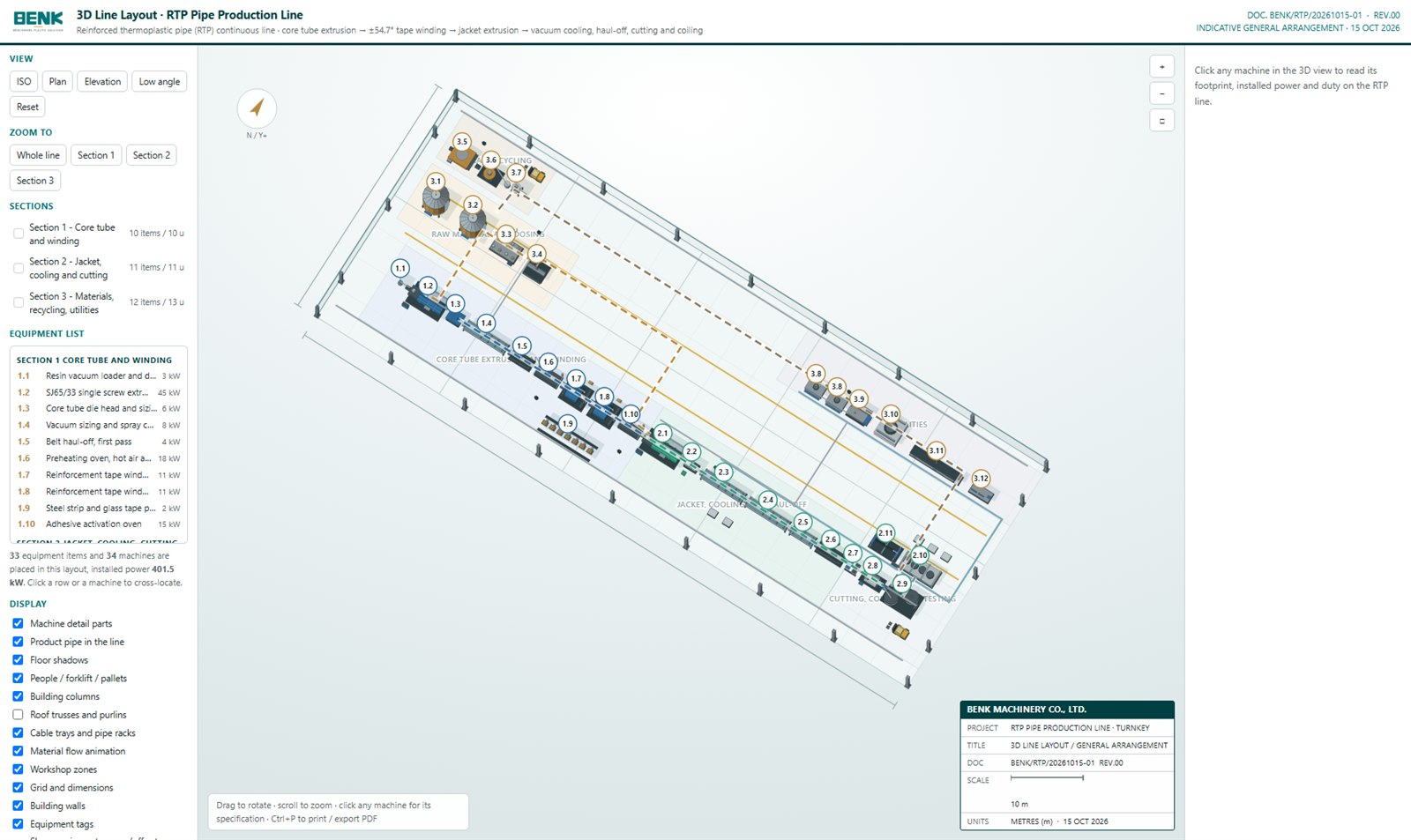
This is the actual general arrangement of the RTP line, drawn in 3D from the equipment list and the machine positions. Drag to rotate it, scroll to zoom, click any machine for its footprint, installed power and duty, and use the Zoom to buttons to jump to a single section. The layout is drawn to scale in metres, so you can check the operating aisle, the coil handling space and the maintenance clearance against your own building.
3D Line Layout · RTP Pipe Production Line
INDICATIVE GENERAL ARRANGEMENT · 15 OCT 2026
| PROJECT | RTP PIPE PRODUCTION LINE · TURNKEY |
| TITLE | 3D LINE LAYOUT / GENERAL ARRANGEMENT |
| DOC | BENK/RTP/20261015-01 REV.00 |
| SCALE | NTS |
| UNITS | METRES (m) · 15 OCT 2026 |
Equipment, as built in our works
The machine family this line is assembled from, photographed in our assembly hall: extruder, vacuum and spray cooling tanks and the line control cabinet — together with the pipe that comes off the end of it.
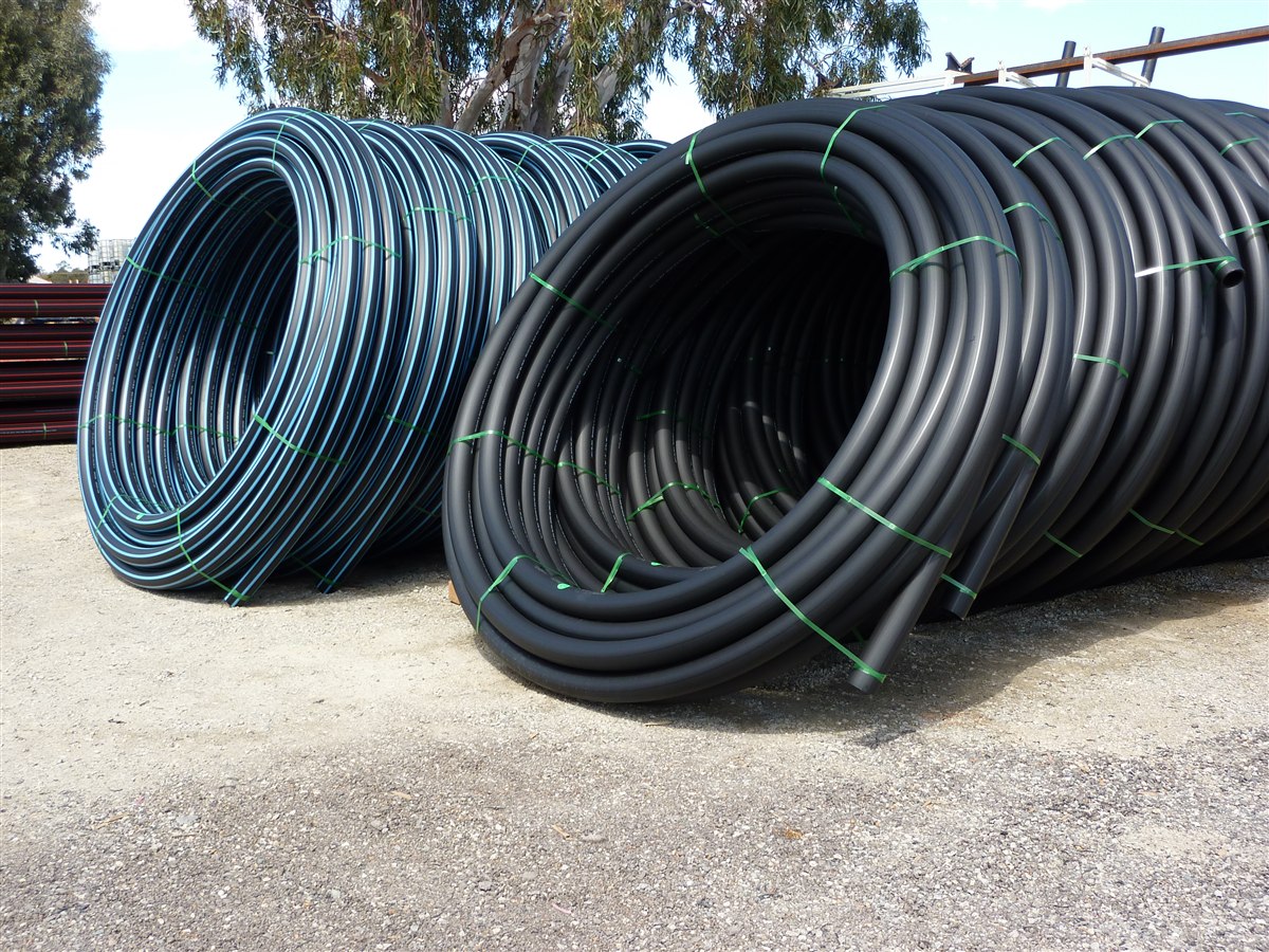
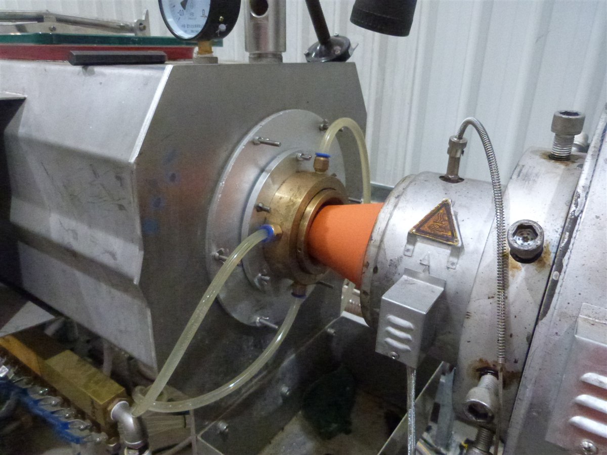
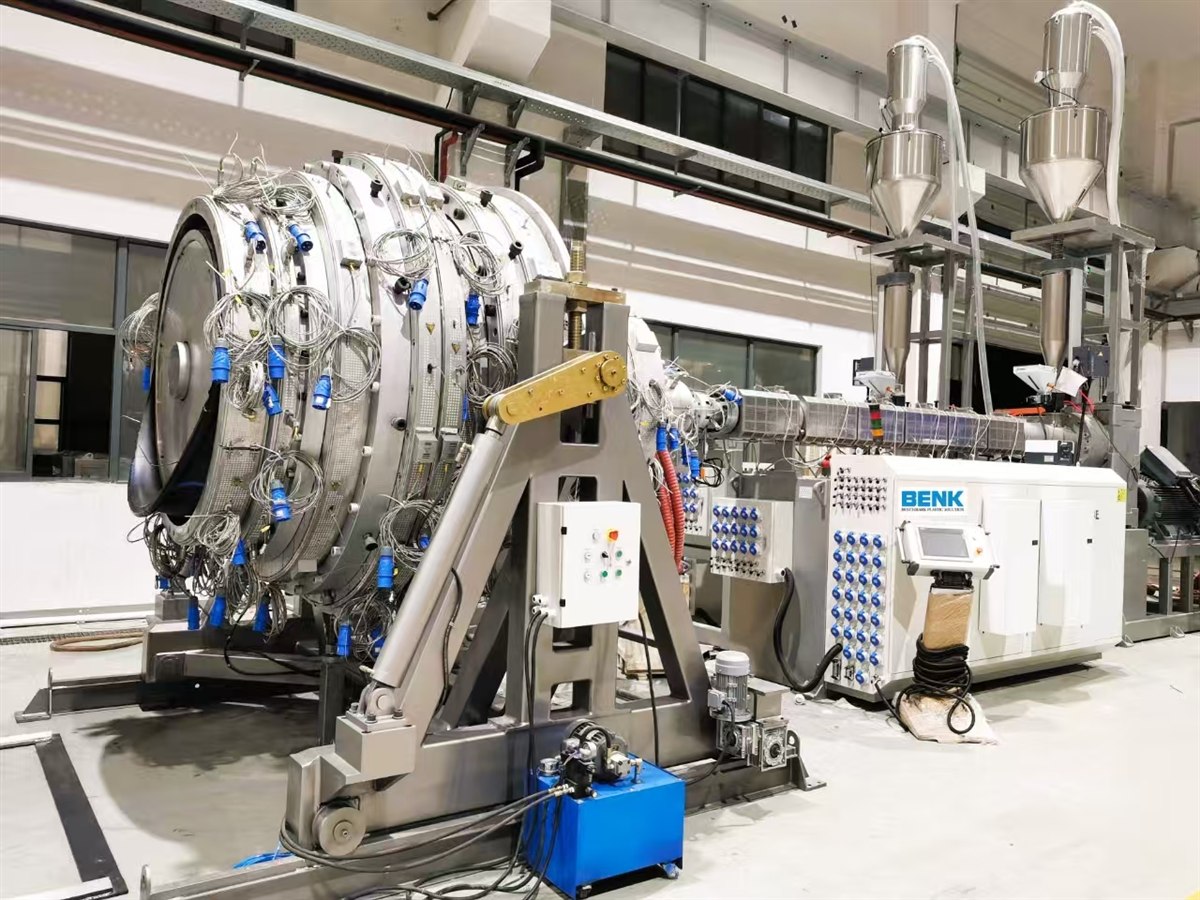
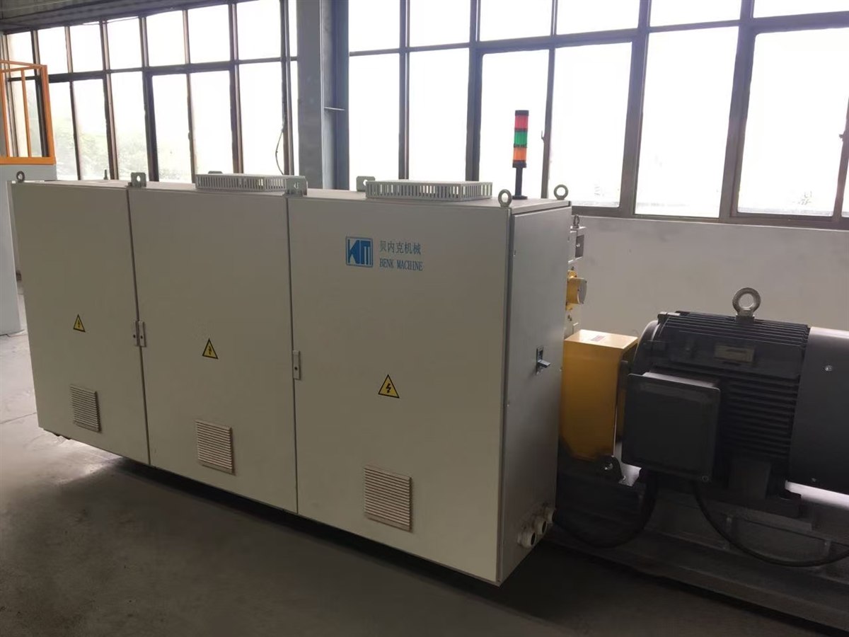
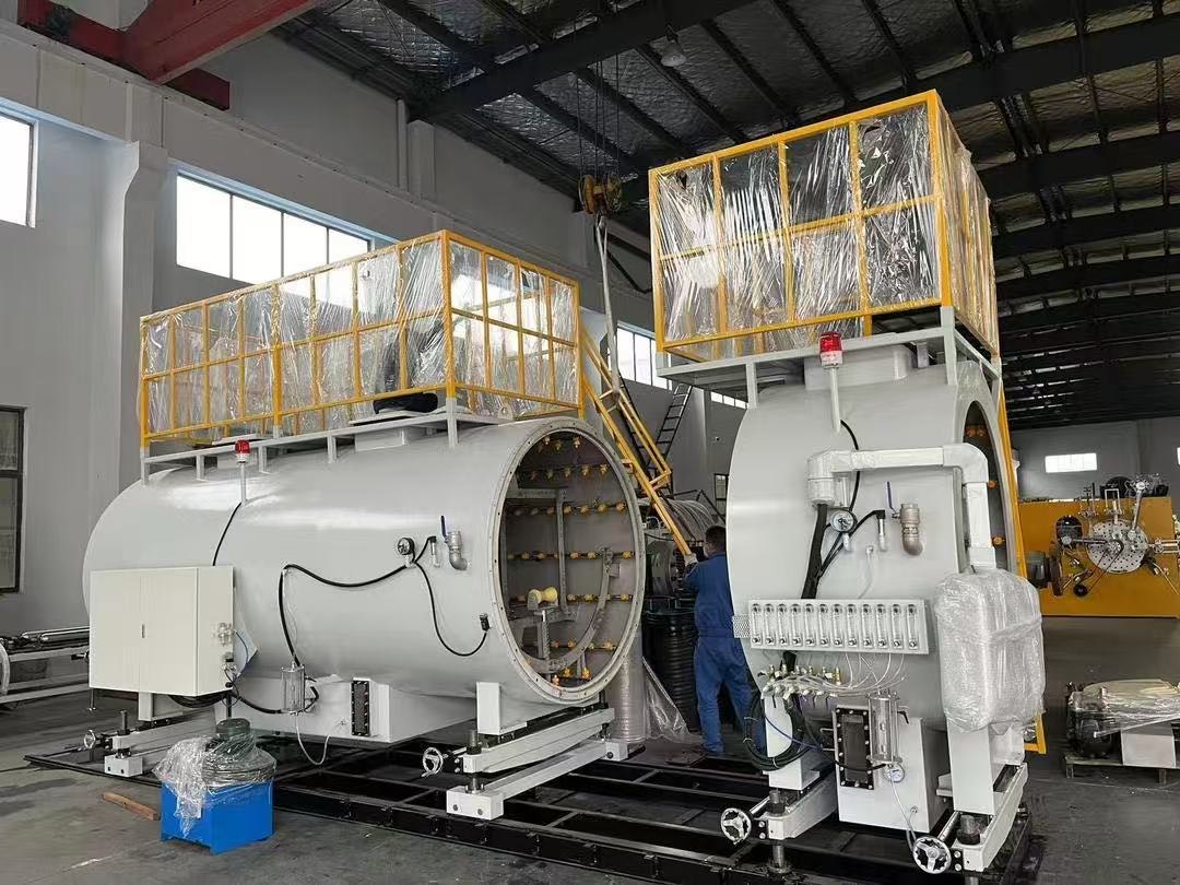
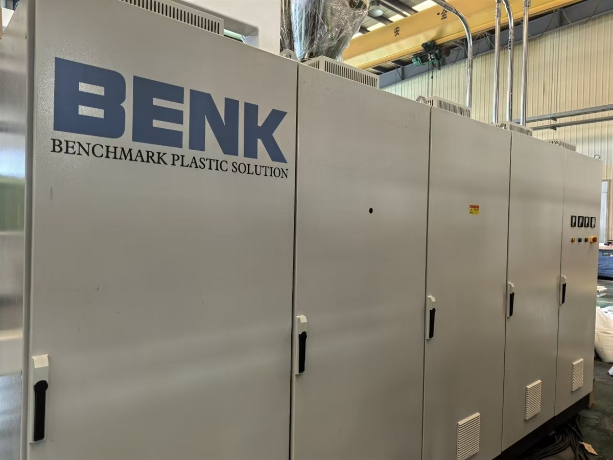
Machine photographs are BENK works photographs. The coiled pipe and die head photographs are by GordonJ86 via Wikimedia Commons, CC BY-SA 4.0.
Where RTP pipe is used
Spoolable composite pipe replaces steel where corrosion, joint count or installation time drives the cost of a line.
Oil and gas gathering lines
Multiphase gathering and injection lines where the fluid is wet and corrosive. The pipe arrives in coils, so a 5 km line needs a few joints instead of hundreds of welds.
Water and gas transmission
High pressure water transmission and gas distribution where trenching time and joint integrity dominate the installed cost.
Chemical and industrial process lines
Corrosive and abrasive process fluids, and temporary or relocatable process lines in plants and terminals.
Mining, slurry and tailings
Abrasion resistant slurries and tailings lines, where the pipe can be re-laid and re-routed as the working face moves.
District heating and geothermal
Insulated or bare service pipe and reinjection lines for geothermal and district heating networks.
Offshore and marginal fields
Flowlines and jumper lines where a spoolable pipe can be installed from a small vessel instead of a lay barge.
Options and auxiliary equipment
Selected against your pressure class, resin system and automation level.
- Second pair of winding heads for 4 – 8 reinforcement layers
- Aramid, polyester or hybrid reinforcement instead of steel strip
- Melt pump and automatic screen changer on the jacket extruder
- Gravimetric dosing and mixing with 0.3 % accuracy
- In line ultrasonic wall thickness scanner with trending
- Automatic coil strapping, wrapping and label printing
- 12 m straight length cutting and stacking line for large diameters
- Pipe end beveling station and coupling fitting supply
- SCADA package with production, scrap and pressure test reporting
- Automatic coil ejection and coil handling conveyor
- Remote diagnostics package with modem and service tunnel
- First fill spare parts and tooling package
Why BENK
One supplier for the whole line
Extruders, dies, winding heads, cooling, haul-off, cutting, coiling, testing, silos, conveying, recycling and the utility block come from one contract, with one set of interface drawings.
Machining and assembly in house
Screws, barrels, die bodies, winding rings and machine frames are machined and assembled in our own works, so spares and geometry changes are not dependent on a third party.
Factory acceptance test
The line is assembled and run on PE100 in our works before shipment. Your engineer is invited to witness the trial run, the winding trial and the pressure test.
Turnkey project management
Layout drawing, foundation plan, utility list, electrical load schedule, installation supervision, commissioning and operator training are part of the delivery.
Recipe development on the line
Winding angle, pitch and tape tension are developed on your line with your pipe specification during commissioning, and stored as recipes in the control system.
Service and spare parts
Installation and commissioning engineers, wear parts kits, remote diagnostics and a documented maintenance schedule for the winding heads, dies and gearboxes.
Questions buyers ask about this line
What pipe sizes can this RTP pipe production line produce?
How many reinforcement winders do I need for a high pressure pipe?
Can one line run steel strip, glass fibre tape and aramid tape?
What output can I expect from the line?
How is the pipe verified before it leaves the line?
How long is delivery, installation and commissioning?
Tell us the pipe, we will confirm the line
Send us your pipe size matrix, pressure class, reinforcement material and the output you need. We will come back with the line configuration, the extruder and winder selection, the utility load, a layout drawing and a quotation.
- Telephone
- +86 512 5896 1463
- Mobile / WhatsApp / WeChat
- +86 159 5096 2426
- kpm@benkpm.com
- Works
- Zhangjiagang City, Jiangsu Province, China
Related lines
Large Diameter PE Pipe Line315 – 1200 mm PE pipe
Pipe & Irrigation LinesFull product family
© 2026 BENK MACHINERY CO., LTD. · RTP pipe production line · reinforced thermoplastic pipe equipment. Figures are indicative engineering values and are confirmed in the technical proposal.